
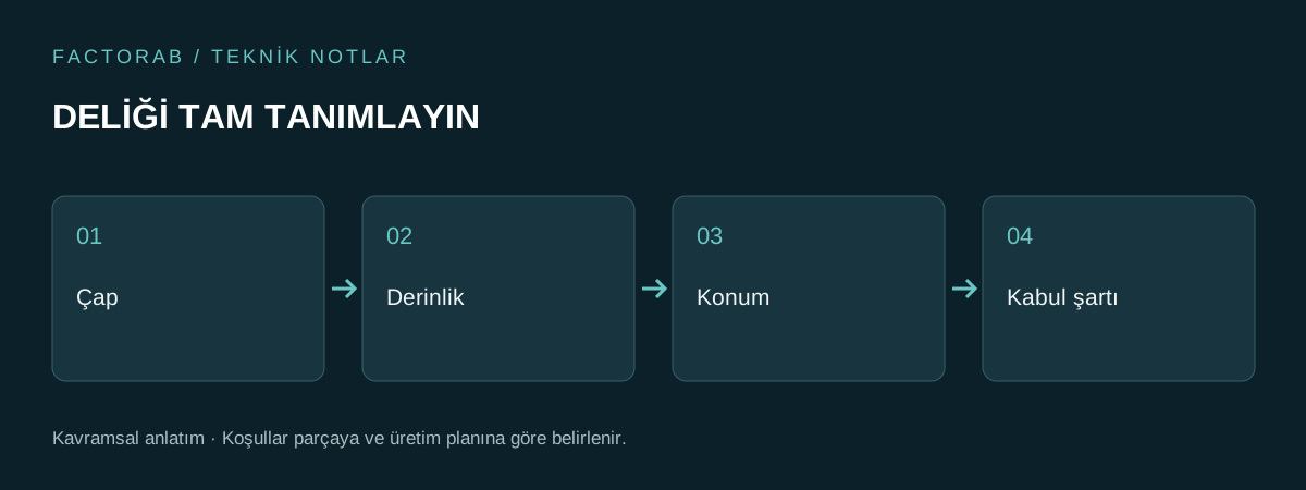
Where does the hole start, where does it end?
The hole through the blind hole is not the same recipe. With the depth at which the full diameter is required in the blind hole, the bottom zone formed by the cutting tool should be separated. The sloping of the entrance and exit, intersecting with another hole, or opening to a region that can remain burr also affects the operation.
When checking the drawing, don't only see the piece from the outside. Add the necessary cross-sections. A detail that is clear to the designer who knows what the hole does in assembly may remain unclear from the manufacturer's point of view.
Access changes along with depth
When the depth increases, it becomes more important to gain access to the cutting tool and remove the chips from the hole. Walter's hole-processing guide is a reference source that evaluates the selection and application conditions of the cutting tool together. The data in the guide should not be read as a guarantee of production independent of the part.
Instead of suggesting the same cycle or the same cooling approach to each deep hole, the material, cutting tool and machine conditions should be examined together. If depth is functionally held more than necessary in the design, it may be useful to ask again why.
Drilling and providing the final measure may not be the same stage
Depending on the required diameter, geometry and surface finish, drilling may need to be followed by a finishing operation. A note saying precision hole is not enough: define the acceptance criteria and let the manufacturer propose an appropriate method.
Measurement access should also be noted. A measurement in the mouth of the hole does not spontaneously prove to give the same result over the entire depth. The region and feature to check, the Report Request It should be clearly included.
Information set to be sent to the manufacturer
- The diameter, depth and length of the transition state.
- References and tolerances to which the location depends.
- The thread standard, class and required effective length, where applicable.
- Critical entry, exit, bottom and burr conditions.
- Measures that will be valid after the final procedure.
This information with current model and technical drawing Share it together. FactorAB Examples of operationsIt shows how holes can be involved in the flow of turning and milling.
Sources and further reading
- Walter Tools Hole processing technical guide
- Protolabs Network Design guide for CNC
- TITANS of CNC TITAN-201 control form sample
This article is an original narrative that deals with technical principles in resources through the process of parts and bids. Examples are for disclosure purposes; it does not mean partnership with resource organizations or their approval of FactorAB.