Swiss-type turning
Mass production on Star CNC machines for rod-fed, multi-operational parts.
- Long and thin geometries
- Turning and rotary cutting tool operations
- Repetitive production needs

Examine our Swiss-type CNC, mill-turn and precision CNC lathe capabilities The production method is determined by technical drawing, material and quantity.
01 MANUFACTURING CABLES
The method of production suitable for your geometry.We evaluate materials, geometry and quantity information together; we determine the appropriate processing approach for your part.
Mass production on Star CNC machines for rod-fed, multi-operational parts.
Nakamura infrastructure that combines turning and milling operations in the same production flow.
Production of parts that address measurement, surface and geometric requirements through technical drawing.
GEOMETRIDEN OPERATION
Technical Drawing Processing Plan ControlAn angled hole, a milled surface, or a detail on the back changes the cutting tool approach, working order, and measurement method. Study how the production plan is set up over nine samples.
We combine operations according to the geometry of the part. The following scope shows model capabilities and processes that require proper cutting tools; the method to be applied to the part is determined through technical drawing.
Basic geometry of shaft, horoscope, pin and fittings.
The hole diameter, depth and position are handled together with the measurement plan.
Cutting diameter, cutting tool length and accessible surfaces limit operation.
During transfer, the holding surface, clamping force and references are planned to be maintained.
| Operation Group | Star SR32 Type B | Star SR38 Type B | Star SB20 | Nakamura WY100V |
|---|---|---|---|---|
| Turning, facing, grooving, threading and parting off | With the appropriate cutting tool | With the appropriate cutting tool | With the appropriate cutting tool | With the appropriate cutting tool |
| Axial hole, bark, ream and guide | With the appropriate cutting tool | With the appropriate cutting tool | With the appropriate cutting tool | With the appropriate cutting tool |
| Radial hole and live tool milling | Rotary Cutter Tool | Rotary Cutter Tool | Connected to the cutting tool unit | Rotary Cutter Tool |
| Off-center hole / surface treatment | Depends on axis and holder | Depends on axis and holder | Depends on variant and holder | Y-axis turrets |
| Angled hole / milling with B axis | No axis B specified | B axis | No axis B specified | No axis B specified; angle holder is also evaluated |
| Back-side processing with main / counter spindle | Counterwork Shaft | Counterwork Shaft | Variant and installed equipment | Two mutual spindles |
| Parallel operation planning | Front / rear processing | Front / rear processing | The board is connected to hardware | Two turrets / two spindles |
Machining external threads with a dedicated thread-whirling unit. This is a manufacturer option for the Star SR32J III; it is not presented as a standard service unless the installed unit is confirmed.
The creation of multi-point screw female geometries with the special polygon unit. It is not the same method as flat surface milling; the control function and the cutting tool unit are evaluated together.
With suitable control functions, axis combinations and live tooling, operations such as contouring, circumferential grooving and thread milling can be assessed. Software and installed equipment compatibility must be checked separately.
The channel broaching and angled cutter tool holder is in our existing hardware. Internal duct / wedge channel brooching and angled hole / milling operations are planned according to the cutter tool profile, access, material and part geometry. The CNC machine and angle of approach for which the gripper will be used are determined on a piece basis.
Channel broaching and angle cutter tool holder are available. With the full variant of SB20, whirling and polygon units must also be verified. The presence of a process in the list does not mean that it can be applied to every material, angle, tolerance and geometry. Grinding, honing, erosion, heat treatment and coating are not included in the direct operation scope of these CNC machines.
Manufacturer sources: Star SR32J III Type B · Star SR38 Type B · Star SB20R Type G · Nakamura WY100V
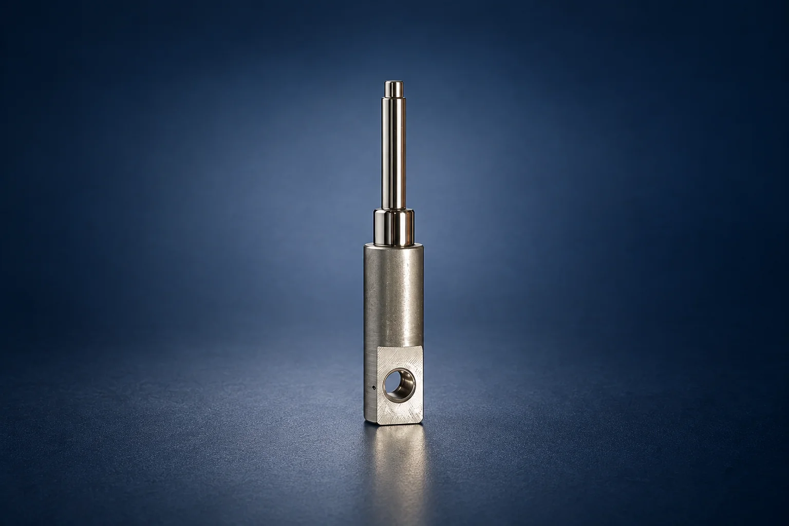
Turning + radial hole
Gradual diameters and the hole on the block are examples of a joint evaluation of the drill operation by turning.
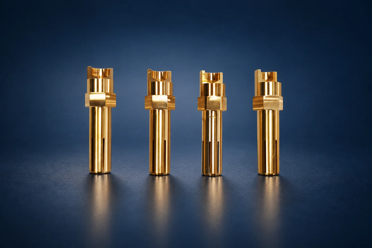
Turning + channel milling
The slot and gradual shaft form in the head area adds live tool operations to the turning flow.
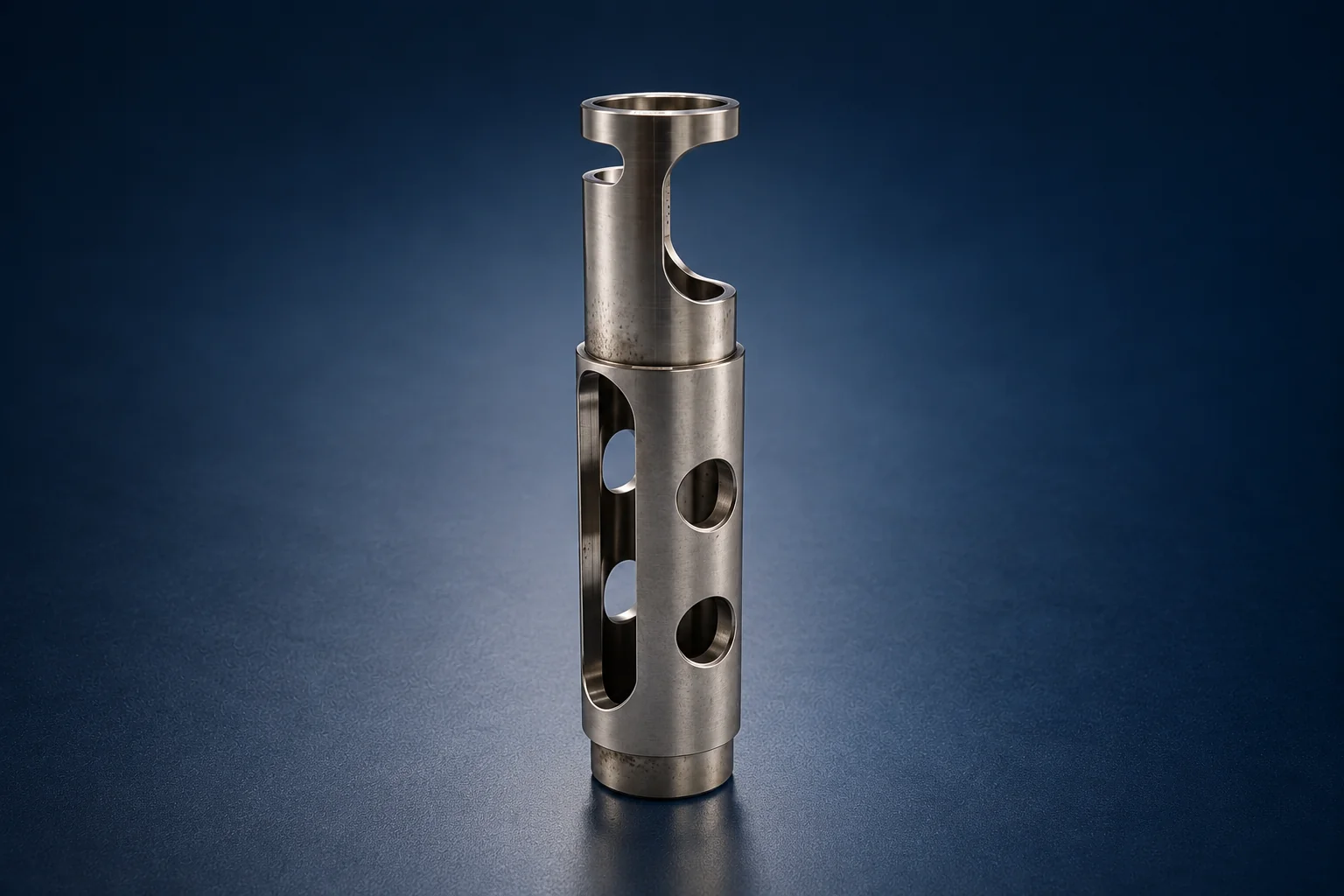
Internal / screw female turning + hole + machined pocket
Inner space, side windows and holes require that thin cidar and cutting tool access be planned together.
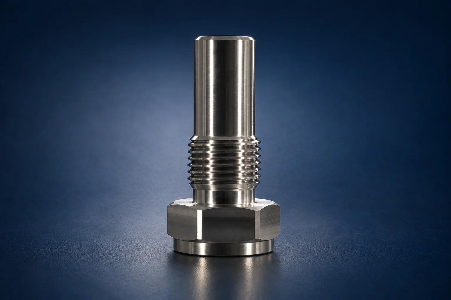
Screw Female Turning + Flat Surface Milling
Screw female screw thread, cylindrical end and wrench flats show the different operation needs of a single part.

Profile turning + inner hole
The connection profile, circumferential steps and internal passage affect the cutting-tool profile and the sequence of internal and external machining.

Internal / screw female turning + backside processing
The flange, inner diameter and forehead surfaces on both sides provide an example of transfer and reference protection.
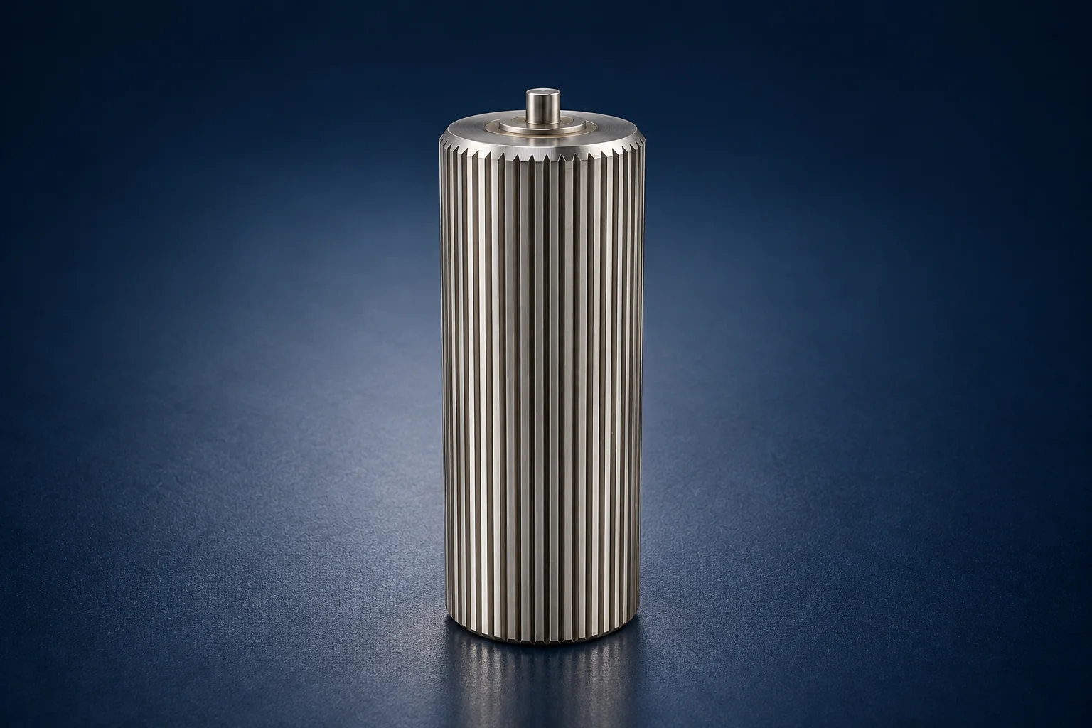
Turning + special surface cutting tool
The screw female surface texture requires evaluation of the appropriate caterpillar or form cutter tool in addition to turning.

Contour turning + circumferential groove
Global ends, neck regions and channels require that cutting tool geometry and profile transitions be handled together.
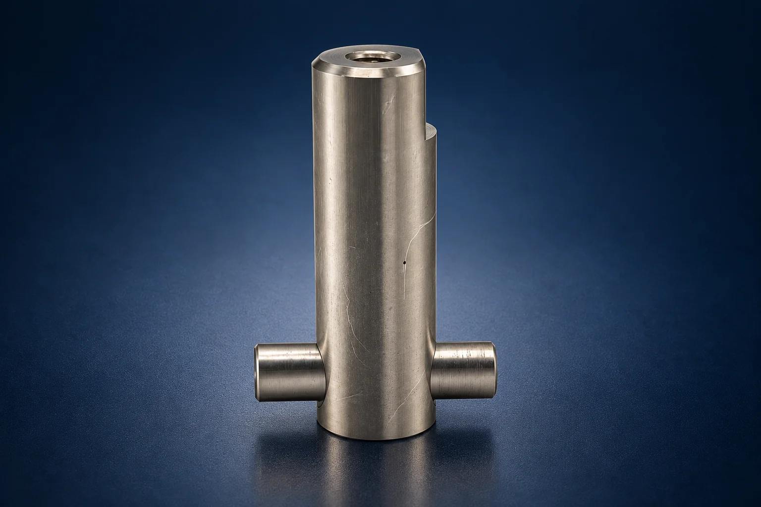
Body processing + side link assessment
Side-linked appearance requires an explanation of the combination form in technical drawing. The visual alone does not indicate whether the part is produced from a single body or by assembly.
References, angles, tolerances and surface requirements in your technical drawing determine the actual operation plan.
Share your technical drawingThe technical drawing and model are evaluated together. The appropriate order of operation is determined through critical measures, surface expectations and the need for delivery.
Share your pieceINTERESTING TECHNICAL WRITERS
As well as the CNC machine name, geometry, workholding and quantity are also decisive.
Explore our services by manufacturing process, material and part type.